A Current Topic 1
Click here for a PDF Download of this article.
A Current Topic
Caution about Overloading Electrical Systems
By Steve Watson
Once we start changing parts on our rides it seems that they are never done. There are always new, bigger,
brighter and more powerful products coming on the market. Many are visual improvements or reflections of
personal taste. Still others are aimed to provide us with more creature comforts, such as air conditioning,
stereo systems, power windows and power seats. Items like high wattage headlights and taillights help by
making our ride safer -the ability to see and be seen is very important.
Putting on a new set of valve covers is pretty much a no-brainer. But when we add horsepower, it is imperative
that we consider the possible affects upon the other components of the drive train so as not to overload
anything. And yet even more important, but often overlooked, is the same potential for overloading electrical
components with new added goodies. Overload the U-joints and they brake -inconvenient but repairable.
Overload an electrical circuit and you could experience a meltdown and possible fire that could take your whole
vehicle.
To that end, we want to discuss three specific areas of the electrical system -switches (like the headlight switch
and ignition switch), connections (like wires and terminals) and the alternator.
A River Runs through It
No, we’re not going to review the movie! We wanted a catch phrase to remind you that electrical current “flows”
kind of like water in a river. The speed of the flow will vary (based upon the voltage pressure pushing it and the
resistance holding it back) but the flow volume at any point in the river is pretty much the same. In the electrical
river, called a circuit, the current flow is exactly the same at all points of the circuit, excluding any branches.
So, if the main load in the circuit is drawing 20 amps, every other component of that circuit will also have 20
amps flowing through it -the fuse, the switch, the wires, the terminals, the ground, everything.
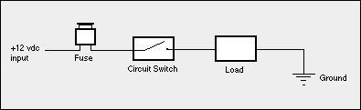
Every part of a simple electrical circuit carries the
same amperage as the load, from initial feed wire all
the way through to the load.
Now consider the case of running two loads off the same feed, such as a pair of driving lights fed by the same
fused source and switch. If each light draws 15 amps, the fuse, switch and primary feed will carry 30 amps -the
sum of the two circuit branches.
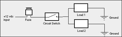
In a branched, parallel load type circuit, the feed
wires, connectors, fuse and switch will carry the
sum of the amperage drawn by each load. Know the
amperage load and size components accordingly.
The most frequent problems brought to us this season had to do with overloaded switches, specifically the
headlight switch and the ignition switch.
Have you heard ( or maybe said) any of these? “My headlights are dull and keep getting worse. Why would
that be?” Or, “My headlight switch gets hot after about a half an hour. What’s going on?” And my favorite
comment, “I put some of those real bright halogen headlights in my car and now some really funky things are
happening -even my turn signals don’t work right!” All of these complaints point to the same problem -the
amount of amperage going through the headlight switch and the resultant effects. Remember, that one switch
feeds multiple circuits.
Typical headlights these days are rated at 55 watts to 70 watts each on high beam. Two units then will pull 110
to 140 watts or as much as about 12 amps (140 watts /12 volts = 11.7 amps). High powered 100 watts
halogens will draw nearly 17 amps. Add some additional juice for the taillights and other running lights and it’s
pretty easy to be putting 20 amps through a headlight switch. Unfortunately, the most common aftermarket
headlight switch is only rated at 15 amps! It’s no wonder why it starts getting hot or won’t feed enough
amperage to keep those lights bright. And in a worst case scenario the switch will completely fail and leave you
literally in the dark.
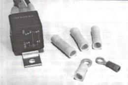
Relays -we’ve all heard about them, but what do we
do with them? Think of this relay as a remote, high
amperage switch. We can replace a “weaker” original
switch with a relay and then use the original switch
as a trigger to turn the relay on. The net effect is
reduced amperage stress on the original switch and
increased switching power and dependability from
the relay. This 70 amp relay, from Watson’s
StreetWorks, makes a great relay for the ignition
switch accessories. It has 10 gauge wire power feeds
and the connectors to make installation a breeze.
So, what-are-ya-gonna-do? Put a relay in the circuit of course. As a reminder, a relay is a “switched-switch” or
“triggered-switch” which is capable of handling higher amperage than the switch it’s replacing. A typical relay
only needs about 120 milliamps (0.120 amps) to be triggered and held closed but can then supply 30, 40 or
more amps (depending upon the relays rating) to the load being fed. By making the relay the main switch in the
headlight circuit and using the headlight switch as the trigger for the relay, we shift the amperage load off the
headlight switch and onto the relay which is designed to do the job.
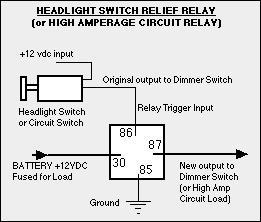
Wiring in a relief relay for the
headlight circuit feed is quite
straight forward and will make
sure the lights get full power.
In our high wattage headlight example used earlier, either a 30 or 40 amp relay will be sufficient to handle the
nearly 20 amps used by the lighting system. For ease in wiring, we recommend only feeding the headlights
themselves through the relay and leaving the lower amperage running lights fed by the headlight switch. But if
you’ve had a problem already, don’t forget to replace the headlight switch with a new unit. Excess amperage
and the resulting heat can corrode switch contacts and cause problems down the line.
There Are Other Problems, Too
Similar ignition switch problems are definitely on the increase. Why, you may ask? The ignition system doesn’t
pull very much amperage and the starter is run through the starter solenoid (which also acts as a relay!), so
what’s the problem? Accessories! You’ll recall that all of the circuits in your car come through the fuse panel
and are either battery fed (on all of the time -like the headlights, brake lights, horn, etc.) or ignition fed (on only
when the ignition is on -like fuel pump, heater, A/C, radio, etc.). This last group, the accessory circuits, are all
routed through the ignition switch.
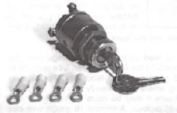
Ignition switches were never intended to carry the
juice we feed through them due to added accessories.
This unit also from Watson’s StreetWorks is one of the
highest rated at 30 amps and is available with a
machined billet nut with C-ring (not shown).
Let me tell you about our very good friend, Dale, who often helps us out in our booth at some of the shows we
do. Dale arrived at the last show with a problem. While en route to the show -A/C on full, radiator fan churning,
tunes on the stereo -the accessory terminal on his ignition switch got so hot that it melted right off . It wasn’t
able to take the total amperage being drawn through it and result was heat and failure.
If we start adding up typical amperage loads for accessories the total gets surprising -fuel pump, 10 amps;
heater/defroster, 15 amps; windshield wipers, 15 amps; A/C, 30 amps; power windows, 15 amps; radio, power
seats…the list goes on and on. Fortunately, not all of these items are in use at the same time and some may
have their own built-in relays. But the cumulative effect still puts a tremendous strain on your ignition switch,
which is seldom rated for over 30 amps.
We’ve even known of two different guys who thought they were experiencing the classic hot start problem
when in fact it was due to their ignition switch. After running the car for a half hour or more they shut it off, may
be to get gas for example, then get back into the car…and it won’t turn over. Or sometimes it will turn over but
not start (particularly with electronic ignitions). Persistent detective work with a volt-ohm meter shows that the
ignition switch is getting a 12 volt supply but only giving up 8 or 9 volts to the starter and ignition feeds. Not
enough to get the job done. Especially with many of the new electronic ignitions that need about 11.5 volts
minimum to work at all.
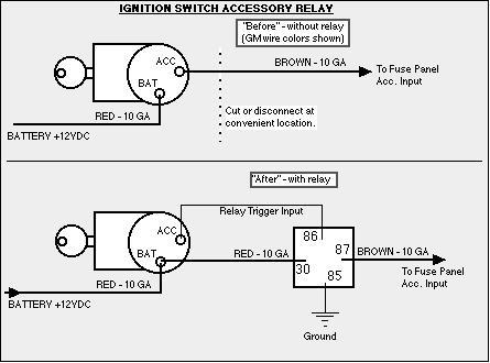
The answer (excuse me while I get back on my soapbox) -put a relay in the circuit. But this time we
recommend a 70 amp relay to cover all of those electrical goodies. The ignition switch will trigger the relay off
of the accessory (ACC) post and the relay will feed the fuse panel accessory input. Hey, it’s not rocket science
but it sure could help you to keep your ride flyin’ high.
Now, in the above example of our friend Dale, another item to consider is the terminal itself and the feed wire
size. Wires and terminals come in a variety of sizes for a reason. Higher amperage circuits require bigger wire
and terminals of higher ratings. The same is true if you are running an extra long circuit or bundling many
circuit wires together in a loom. Just like the switches, these parts need to be sized to carry the amperage and
need to be able to ventilate to prevent heat buildup. Soldered connections are not necessary -a good crimp
joint is fine. In fact, amateurs can overheat solder joints and cause a brittle solder. The OEM’s as-a-rule use
crimp joints for everything including many main battery connections. Again, every single piece in a circuit has
the total amperage running through it and needs to be sized accordingly.
A relay in the ignition switch accessory feed wire will
prevent a lot of possible problems. These before-and-after
diagrams show how easy it is to do.
Finally, a quick word about your alternator. (Feel relieved, there is no mention of a relay here.) With all of these
amperage hungry lights and accessories, you may have experienced the idle-speed-low-chargin’-blues. Hot
day, A/C on, sitting at the stop light with the battery discharging…what a bummer.
The usual answer, to borrow from TV, is that we need “more power” so we run out to buy a 100 amp alternator.
Buyer beware. Big numbers aren’t always were it’s at. It’s not the maximum possible output of the alternator
that we need to know (100 amps at some driving RPM) but rather the amperage output at idle speed where the
problem exists! Said differently, what does the amperage-to-RPM output curve look like? The flatter the curve,
i.e., the more uniform the possible amperage over a broad range of RPM’s, the better. Top alternator suppliers
will provide an output curve or chart to support their product. Ask before buying and you will be more likely to
get the product and results that you want and need.
And to feed all this new amperage from the alternator to the rest of the car, let’s upgrade to an 8 gauge primary
feed wire. For existing wiring where you already have a 10 gauge feed wire it may be more convenient to add
than to replace. A second 10 gauge wire can be added along side the first but be sure that all of the
connections and terminals are right to do the job.
Electrical system problems can be some of the most frustrating and difficult to solve. But if we approach
electricity with knowledge and remember to consider the effects of one small (?) change upon other
components and upon the whole system, we’re more likely to keep our ride on the road, safe and running the
way it should.
SOURCE:
Watson’s StreetWorks Rod & Custom Products
4 Bud Way, Suite 3
Nashua, NH 03063
Phone 603-943-7923
www.Watsons-StreetWorks.com
Click here for a PDF Download of this article.
Well written article . I’ve done the thing to work added horns on my pick up truck. I use the original horn wire to fire a 30a. relay then run #10 wire to the horn tabs from the battery ( fused ) . For my ‘64 Galaxie I’m going to relieve the ignition switch of most of its duties,
likewise the headlight switch also . Hard finding the relays with the mounting tabs tho.
Thanks much ,
Bob