Rewiring the Beetle in Style 1
Here’s the PDF Download of this article.
Rewiring the Beetle in Style
Almost from the first day that a Beetle drove the roads, VW restoration products were needed. Now
don’t get us wrong. VW’s weren’t built to break down. They were a car for the people…Folk’s wagons.
But for that very reason, they got used…and used, and used. And as a result they needed repair. And
as they aged, they needed restoration. But as well designed and as simplistically engineered as the
mechanical parts of a Beetle were, their electrical systems were not. Well, actually, that same
simplicity may actually be the problem with their electrical systems.
Early VW wiring was all battery fed…it was always ON. Those early Germans didn’t know of drive-ins
or parking. So, the radio, turn signals and wipers, for instance, ran off of direct battery feed and had to
be shut off independently from the ignition switch. And, once those VW engineers determined that
everything could be battery “hot” fed, they also could route wiring wherever they wanted. (Read that
to mean – route wiring to the closest spot for subsequent distribution without logical engineering
rational.) One point of example..why does the primary battery feed go to the headlight switch first?
American wiring takes a different approach which we like to refer to as the tree trunk approach. (A)
Battery primary is fed directly into the fuse panel for those circuits which require it. (B) Also feed
battery primary to the ignition switch and then feed, secondarily, the accessories to be controlled by
the ignition switch. And (C), route all circuits through a fuse and then to the load (lights, coil, starter,
etc.). This tree trunk approach provides a common feed for always-on (battery) circuits that branches
off through fuses to the individual circuits and also for the on-only-with-the-ignition (accessory)
circuits. Now, that’s logical. It also makes for much easier trouble shooting should an electrical
problem pop up.
Two other considerations of original VW wiring are visual esthetics and safety. Visually, the back side
of the VW fuse panel tended to resemble either a cross-legged centipede or a porcupine having a
bad quill day. Wires went everywhere without obvious sense. Not something that you could make to
look “show quality”. And most connectors are bare terminals just waiting to short circuit on your
unsuspecting screw driver or hand.
O.K., so we need a new wiring system in our Bug and we want something modern, safe, good
looking, easy to trouble shoot, uses ATO/ATC fuses…the whole nine yards. Who ya’ gonna’ call? Call
Watson’s StreetWorks and check out their VW Beetle Modular wiring kit. This state-of-the-art system
gives you 18 circuits, a safe, modern fuse panel, color coded and line-marked wires, terminals,
detailed, easy-to-follow instructions/schematics…almost everything you need to rewire and upgrade
your Beetle’s electrical system. So, let’s get started with the project. Check out the photos, especially
the before and after shots. Wow, what a difference.
There are a few parts that are not included in the kit, so plan accordingly. There are no switches in
the kit which allows you to keep your originals if you want or to selectively upgrade to new. We
wanted to get away from all of the old design stuff and into modern components so that suited us
perfectly. And switching to an ignition switch that included accessory position seemed the smart thing
to do.
We also wanted to get rid of the complicated and expensive turn signal/emergency flasher relays
which we did. And finally, we are upgrading to a 12 volt system – the details of which we will leave for
another article. Lots of work, but best done all at once in this case.
There are lots of other modifications that this particular V-dub will undergo, but we wanted to show
you what installing this type of wiring kit on a stocker was all about. The process is not difficult, nor
are there special tools required beyond basic wiring stuff, rather it just takes some time. Planning
beforehand and as you go, combined with the kit’s good instructions, will take you step-by-step
through the process.

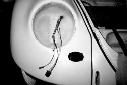
This is our “project” – a six-volt Œ66
Beetle. Looks good from a distance but it
has a long way to go to be what we want.
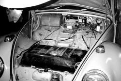
Just pop the bonnet…here’s where we
made our decision to do a major
renovation.
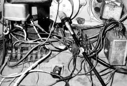
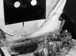
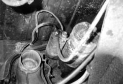
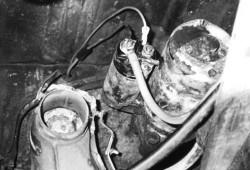
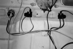
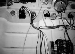
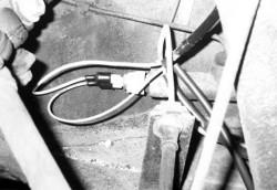
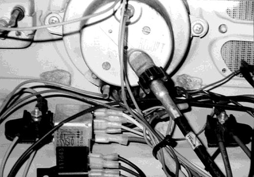
Be brave and take a closer look. The
original wiring was bad enough with wimp
fuses, unprotected hot terminals and no
markings what so ever. But then add
years of amateur owners who have
patched leads, used household wire,
twisted connections and electrical tape.
Top off the spaghetti with the emergency
flasher module and other “black box”
components and it becomes impossible to
digest. Start ripping it out…
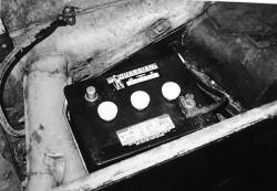
Step one in any electrical project,
disconnect the battery. We’ll donate this
6-volt to one of our antique car friends.
In order to get at everything, we are
gutting the interior. It needs it anyway.
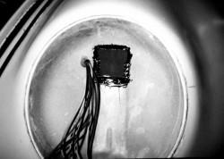
This pile of goop from near the battery
and by the wheel well is courtesy of New
England mice. It has to come out both for
safety and to eliminate that old car smell.

Power to the rear end goes down the driver kick panel, then through and along
the heat box…
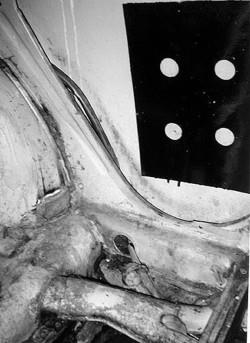
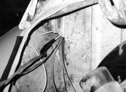
…then back through the rail to go over the
rear wheel well…
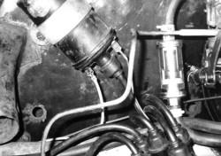
…into the engine compartment…
…across to the passenger side…
…and down to the starter. Note what is
connected where – write it down and make
sketches if needed. Then tear it all out.
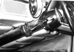
The steering column feed will get pulled
out but retained since we’re not doing a
column swap.
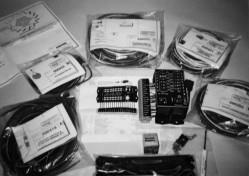
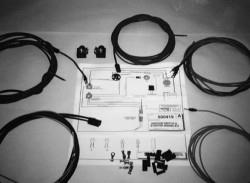
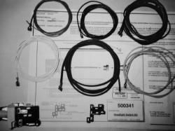
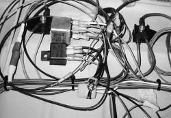
Here is the new kit to be installed. Look at
that beautiful fuse panel. The kit is
extremely well organized in step-by-step
packs, each with CAD drawings and all
the parts to do a specific installation step.
We start by locating the fuse panel. To
provide more room and a better looking
installation we elected to put it straight
forward of the speedometer. We used snap
interlocking fasteners to attach the panel.
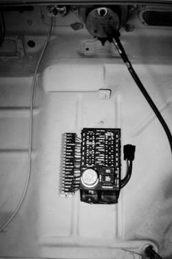
In place, this panel is easy to access with
well marked fuses, connectors,
relays…everything.
Our first wiring will be for the main power
feeds. All of the goodies are in bag “A” with
clear diagrams to show us how.
The new battery hot lead goes to the starter
solenoid and then forward to the fuse panel
through a fusible link for protection. The
other connection is the starter trigger from
the ignition switch.
The voltage regulator battery feed goes
back to the same starter solenoid terminal to
recharge the battery as needed and the
other connection goes forward to the idiot
light to trigger the regulator. The kit is aimed
toward one-wire alternator use, but is easily
adapted to any type charging system.
For ease of wiring now, and for adding
circuits later, this kit provides two junction
blocks. The one on the right is battery fed
power and the one on the left is accessory
power from the ignition switch. A clean way
to hook up the juice.

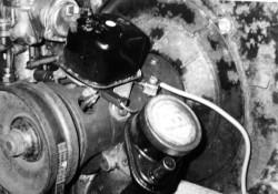
A close up of the ignition switch. This is a
higher amperage unit from StreetWorks – it
fits into the original location, clearing the ash
tray brackets, and has the extra accessory
position. We have added the starter trigger
wire and the ignition feed wire…
…that goes back to the coil. The second coil
connection goes to the distributor.
Street Works wiring kit does not come with
switches, so you can retain your originals if
you want. We wanted a new style headlight
switch and got this OEM style from them.
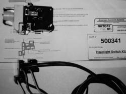
Notice that the headlight switch instructions
give explicit details for where each wire
goes.
Installed in its new location, the headlight
switch wires get routed to the right places.

One of the replacement/upgrades we are
doing is to replace the old dimmer switch
relay with a newer, smaller unit also from
Watson’s. The headlight switch feeds the
relay, which is then triggered by the stock
grounding switch in the turn signal arm.
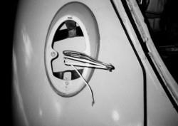
We can then run and terminate the headlight
wires with the sockets provided in the kit.
The individual lead is for the parking light
that is in the headlight assembly.
The driver side headlight bucket has twice
the wires because they go there first and
then jumper over to the passenger side.
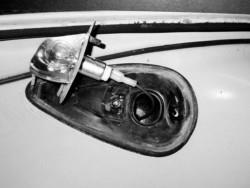
Before reinstalling the seal beams, we
epoxied a rubber pad to the back of the
fender cavity to help prevent any possible
wire chaffing.
While wiring up front, we connected the turn
signals…
…and the brake switch and the horn (not
shown).
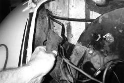
Running the wiring to the back end, we
found that a left over piece of the heavy 10
gauge primary battery feed wire came in
handy. We fished it through the body easier
than small wires and then pulled the whole
bunch in one shot.
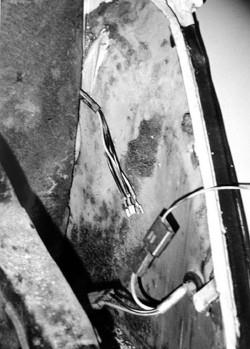
The taillights get wired just like the front end.
Wires on this driver side get jumper wired
over to the passenger side and to the
license plate light.
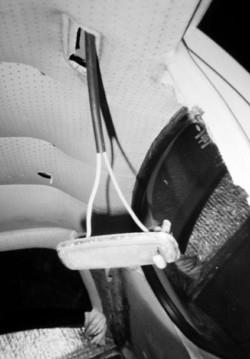
Don’t forget the dome light. We put these
wires inside some heavy wall shrink tubing
and used the old wires to pull the new wires
through the body.

Up front again, we added new terminals to
the steering column wires…
…then routed them to our new 4-way hazard
switch relay and on to the turn signal leads.
We’re using a neat little toggle switch to
activate the 4-ways. Toggle, relay and all
are also StreetWorks items and are much
more straight forward than the original stuff.
Let’s not forget the dash lights, turn
indicators and generator light.
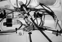
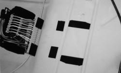
All of those tie-wraps that come in the kit
help to clean up the wiring. On the right of
the photo you can see our master ground
connection attached to the old flasher relay
mount.
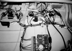
Finishing up under the hood, we have added
the wiper switch on the far left and an
electric windshield spritzer pump close by it,
tie-wrapped wires and have gotten
everything except the fuse panel itself
behind where a protective panel will attach.
The guys are gonna’ be envious of this
setup.
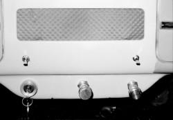
Here is our new switch grouping – ignition, headlights and wiper switches on the bottom;
the toggle over the ignition is for 4-ways and the one over the wiper is for the electrical
windshield washer.
Here’s the PDF Download here.
Thank you for posting this information. I recently purchased a 73 SB and thought I was losing my mind trying to figure out the logical reason for what I was looking at, now I find out it’s just those crazy German engineers, thanks for the push back to reality much better now. Ready to gut the original and put one of your harnesses in , will be calling you soon. Thx!