

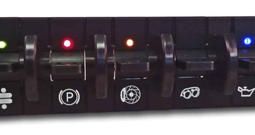
How to Wire Hot Rod Switches
How to Wire Hot Rod Switches: Relay Wiring, Polarity, and Panel Layout Explained
Wiring a hot rod switch panel isn’t hard. But a few small decisions make the difference between a panel that looks good and one that actually holds up. Should the switch break the positive side of the circuit or the negative side? Does the circuit need a relay? What wire gauge does the load really need? Where should each switch sit? Get these right, and understanding how to wire hot rod switches turns from a guessing game into a simple checklist.
This guide covers the choices that matter most: polarity, relays, wire gauge, and panel layout.
Watson’s Streetworks
Article Contents





Positive Side or Negative Side: Pick a Logic and Stick With It
Every switched circuit breaks the flow of power somewhere.
Most hot rod wiring uses positive-switched circuits. The switch sits between the fused power feed and the load, while the load’s other wire runs straight to a chassis ground. This setup has three advantages:
- It’s easier to fuse.
- It’s easier to test with a test light.
- It’s safer if a wire ever rubs through and grounds out, since the switch is already open.
Some circuits use negative-switched wiring instead. Relay coils often work this way. So do a few OEM-style parts. Neither method is wrong on its own. Problems start when one panel mixes both without a clear plan. That’s when a wire lands on the wrong pin, or a circuit works backward.
Before you wire anything, find the automotive switch wiring diagram for your exact switch. Skip the generic diagrams you find online. Wiring layouts change between brands, even when switches look identical. The diagram tells you which pin is hot, which is ground, and which feeds a light.
The LED Polarity Trap
Illuminated switches make this decision even more important. Many lighted rockers and toggles wire the LED to a specific polarity. This is often separate from the load circuit itself. Get the load wired right, but the LED wired backward, and you’ll see one of two problems:
- The LED glows faintly even when the switch is off.
- The LED never lights at all, even when the circuit is on.
Neither means the switch is broken. It means a wiring diagram got skipped.
The fix: pick one polarity logic for your whole panel, then check every illuminated switch against its own diagram before it goes in, not after.
Relay Wiring: Let the Switch Trigger the Load, Not Carry It
A panel switch should do one job: complete a low-current path to a relay coil. The relay’s heavier contacts do the actual switching of the load. This keeps the wire behind your dash light and thin. It also keeps heat and arcing away from something your hand touches. The switch only ever sees a few hundred milliamps, no matter how much current the accessory pulls.
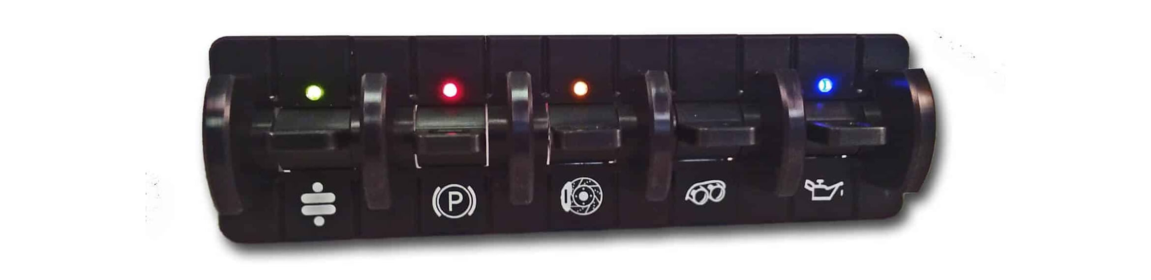
When You Need a Relay
Any circuit with a motor or a compressor belongs on a relay:
- Cooling fans: pull 15 to 30 amps running, and spike higher on startup.
- Fuel pumps: motor-driven, so they load a circuit the same way a fan does.
- Wiper motors: draw a heavy stall current every time they park.
Even a toggle rated for 20 amps steady-state wasn’t built to break that much inrush and arc thousands of times over its life. The contacts pit. Resistance climbs. That’s often why a switch runs warmer than it should. Hot rod switch relay wiring solves this before it becomes a problem.
A 40-amp SPDT relay covers most fan and pump duty. For circuits where you also want to keep the ignition switch from carrying accessory load, a higher-amp relief relay does that job instead. Watson’s stocks relay packs, flashers, and reversing modules sized for this kind of duty.
Momentary vs. Latching Switch Wiring
This is a separate decision from whether a circuit needs a relay.
A latching switch stays wherever you leave it. Most rockers and toggles work this way. A momentary switch only closes while you’re pressing it, then springs back open. Momentary switches are the right choice for anything that pulses rather than stays on, like a horn button, a purge switch, or a starter interrupt. Check out our article on momentary vs. latching switches to learn more.
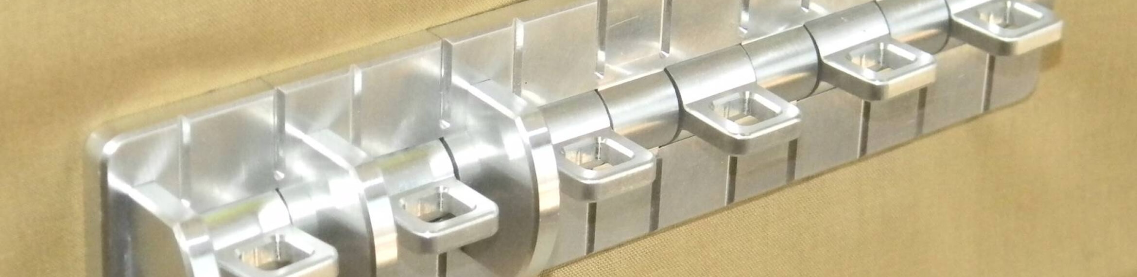
Watson’s Switch Whitch (SW-SW) combines both ideas. It takes a single momentary switch and turns it into a dual-throw circuit. That means one push button can replace an old pull-style headlight switch and still give full on/off control, or run a second function off the same press.
Wire Gauge by Circuit: Size to the Load, Not the Switch
Good hot rod switch panel wiring isn’t just about the switches. It’s also about picking the right wire for each circuit. Once a relay handles the switching, the choice of wire gauge comes down to two questions: what feeds the relay coil, and what feeds the load?
The coil-trigger wire, meaning the switch leg, carries almost no current. Use 18 to 20 AWG, no matter how big the load is downstream. The load leg is where gauge actually matters:
- Dash indicators and LED illumination: 18 to 20 AWG.
- Relay coil trigger wire (the switch leg): 18 to 20 AWG, regardless of the load.
- Power windows and wiper motors on a relay: 14 to 12 AWG, depending on run length.
- Cooling fans: 12 to 10 AWG on the relay-to-fan leg, fused close to the battery.
- EFI fuel pumps: Draw varies by pump, often 5 to 10 amps. Check the pump’s spec sheet before you assume a number, since a long run affects fuel pressure through voltage drop.
Wire gauge follows amps and distance. It doesn’t follow whichever switch happens to sit upstream. A properly relayed circuit means the panel switch never decides what wire goes to the load.
Panel Layout: Group by Circuit Type, Not by Looks
A hot rod dash switch layout should be organized by what each circuit does, not by which switches look good next to each other.
Ignition-Dependent vs. Always-Hot Circuits
Split your panel into two groups:
- Ignition-dependent circuits should only work with the key on.
- Always-hot circuits operate even with the ignition off, such as interior lights or a security system.
Keep these two groups physically apart on the panel. Put one group on top and the other on the bottom, or split them left and right.
This makes it obvious at a glance which switches can drain your battery overnight.
Where the Master Fuse Block Goes
A master fuse block belongs between the battery feed and the panel, not scattered after individual switches. One fused, always-hot feed runs to the block. The block then splits into individually fused circuits before each one reaches a relay or switch.
This matters because a short in one circuit should blow one fuse. It shouldn’t pull fault current back through a switch that was never built to act as one. Watson’s wiring harness kits and fuse block components are engineered around that principle: one clean feed in, individually fused circuits out.
Planning for Future Expansion
Plan for the accessory you haven’t added yet. Leave one or two blank switch positions open, and land a spare fused circuit at the block even before you use it. That way, adding something later means landing two wires rather than re-splicing the whole feed.
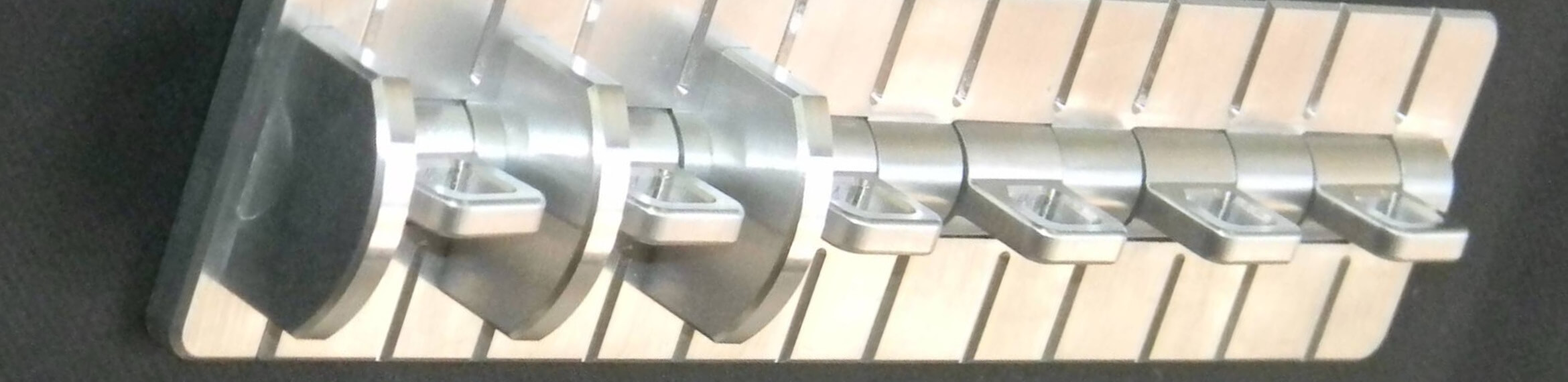
Watson’s SS-series rocker and toggle switch panels come in 2-, 3-, and 4-switch layouts for this kind of planning. Our GT3 and GT4D modular switch systems go a step further. They’re built to accept new switch positions later without tearing into the harness behind the dash.
Labeling and Routing: What’s Behind the Panel Matters Too
Once the dash goes back together, none of this wiring will be visible, not even to you. Do the labeling and routing carefully now, because fixing a mistake later means tearing the dash apart again:
- Label both ends of every wire before it disappears behind the dash.
- Use heat-shrink labels, not tape. Tape won’t survive a hot summer under the dash.
- Keep ignition-dependent and always-hot bundles visually different, by loom color or by keeping them as separate runs.
- Route through proper pass-throughs and wire-routing hardware at the firewall and body seams, not a raw hole in sheet metal.
Secure bundles every 12 to 18 inches so nothing rubs against a bracket or exhaust part over time.
Shop Switches and Wiring for Your Panel
Watson’s StreetWorks carries the switches and wiring parts for your hot rod build, from single replacement toggles to full modular panels, plus the relays, harnesses, and routing hardware to wire them correctly the first time.
Browse our full line of hot rod switches to get started, or reach out to our tech support team with questions specific to your build before you start cutting wire.
Frequently Asked Questions About How to Wire Toggle Switches In a Car
Can I use a single toggle switch to control a high-draw accessory like an electric radiator fan, or do I need a relay?
You need a relay. A toggle rated for 20 amps continuous still isn’t built to handle a fan motor’s startup surge, or the arc that happens every time the contact breaks under load, thousands of times over the switch’s life. Let the toggle trigger a relay coil instead, and let the relay’s contacts carry the fan’s actual current.
What’s the correct wire gauge for a switch that controls a fuel pump on a hot rod with an EFI swap?
The switch leg itself only needs 18 to 20 AWG, since it’s triggering a relay rather than carrying pump current directly. The relay-to-pump leg should be sized to the pump’s actual amp draw, commonly 5 to 10 amps, but different for every pump, plus the length of the run. Check the pump manufacturer’s spec sheet for its real draw before you choose a gauge.
My toggle switch gets warm after extended use; is that a sign of a problem, or is it normal?
Slightly warm under sustained load near a switch’s rated capacity isn’t unusual. Noticeably hot, discolored, or warm to the touch on a circuit that isn’t running through a relay is a sign of a problem: undersized wire, a loose or corroded connection, or a switch carrying more current than it was built for. If a circuit is approaching a switch’s rated capacity, that’s a sign it should be relayed instead.